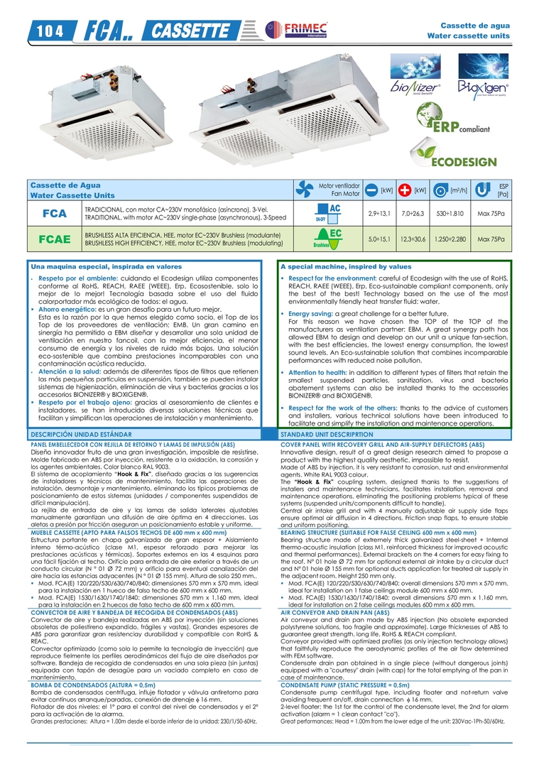
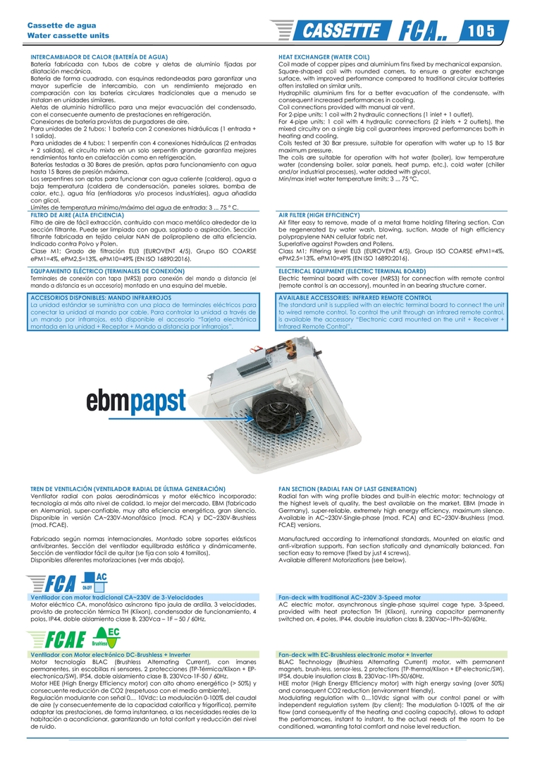
Cassette de Agua  Water Cassette Units  Motor ventilador  Fan Motor  [kW]  [kW]    [m 3 /h]  ESP  [Pa]  FCA   TRADICIONAL, con motor CA~230V monofásico (asíncrono), 3-Vel.  TRADITIONAL, with motor AC~230V single-phase (asynchronous), 3-Speed    2,9÷13,1 7,0÷26,3  530÷1.810  Max  75Pa  FCAE   BRUSHLESS ALTA EFICIENCIA, HEE, motor EC~230V Brushless (modulante)  BRUSHLESS HIGH EFFICIENCY, HEE, motor EC~230V Brushless (modulating)    5,0÷15,1  12,3÷30,6  1.250÷2.280  Max 75Pa    Una maquina especial, inspirada en valores       Respeto por el ambiente:  cuidando el Ecodesign utiliza componentes  conforme al RoHS, REACH, RAEE (WEEE), Erp, Ecosostenible, solo lo  mejor de lo mejor! Tecnología basada sobre el uso del fluido  calorportador más ecológico de todos: el agua.      Ahorro energético:  es un gran desafío para un futuro mejor.  Esta es la razón por la que hemos elegido como socio, el Top de los  Top de los proveedores de ventilación: EMB. Un gran camino en  sinergía ha permitido a EBM diseñar y desarrollar una sola unidad de ventilación en nuestro fancoil, con la mejor eficiencia, el menor  consumo de energía y los niveles de ruido más bajos. Una solución  eco-sostenible que combina prestaciones incomparables con una  contaminación acústica reducida.      Atención a la salud:  además de diferentes tipos de filtros que retienen  las más pequeñas partículas en suspensión, también se pueden instalar  sistemas de higienización, eliminación de virus y bacterias gracias a los  accesorios BIONIZER® y BIOXIGEN®.      Respeto por el trabajo ajeno:  gracias al asesoramiento de clientes e  instaladores, se han introducido diversas soluciones técnicas que  facilitan y simplifican las operaciones de instalación y mantenimiento.    A special machine, inspired by values       Respect for the environment:  careful of Ecodesign with the use of RoHS,  REACH, RAEE (WEEE), Erp, Eco-sustainable compliant components, only  the best of the best! Technology based on the use of the most  environmentally friendly heat transfer fluid: water.       Energy saving:  a great challenge for a better future.  For this reason we have chosen the TOP of the TOP of the  manufacturers as ventilation partner: EBM. A great synergy path has  allowed EBM to design and develop on our unit a unique fan-section,  with the best efficiencies, the lowest energy consumption, the lowest  sound levels. An Eco-sustainable solution that combines incomparable  performances with reduced noise pollution.       Attention to health:  in addition to different types of filters that retain the  smallest suspended particles, sanitization, virus and bacteria  abatement systems can also be installed thanks to the accessories  BIONIZER® and BIOXIGEN®.       Respect for the work of the others:  thanks to the advice of customers  and installers, various technical solutions have been introduced to  facilitate and simplify the installation and maintenance operations.  DESCRIPCIÓN UNIDAD ESTÁNDAR    STANDARD UNIT DESCRIPRTION  PANEL EMBELLECEDOR CON REJILLA DE RETORNO Y LAMAS DE IMPULSIÓN (ABS)  Diseño innovador fruto de una gran investigación, imposible de resistirse.  Molde fabricado en ABS por inyección, resistente a la oxidación, la corrosión y los agentes ambientales. Color blanco RAL 9003.   El sistema de acoplamiento “Hook & Fix”, diseñado gracias a las sugerencias de instaladores y técnicos de mantenimiento, facilita las operaciones de instalación, desmontaje y mantenimiento, eliminando los típicos problemas de posicionamiento de estos sistemas (unidades / componentes suspendidos de difícil manipulación).  La rejilla de entrada de aire y las lamas de salida laterales ajustables manualmente garantizan una difusión de aire óptima en 4 direcciones. Las aletas a presión por fricción aseguran un posicionamiento estable y uniforme.    COVER PANEL WITH RECOVERY GRILL AND AIR-SUPPLY DEFLECTORS (ABS)  Innovative design, result of a great design research aimed to propose a  product with the highest quality aesthetic, impossible to resist.   Made of ABS by injection, it is very resistant to corrosion, rust and environmental agents. White RAL 9003 colour.  The  “Hook & Fix” coupling system, designed thanks to the suggestions of installers and maintenance technicians, facilitates installation, removal and maintenance operations, eliminating the positioning problems typical of these systems (suspended units/components difficult to handle). Central air intake grill and with 4 manually adjustable air supply side flaps ensure optimal air diffusion in 4 directions. Friction snap flaps, to ensure stable  and uniform positioning.  MUEBLE CASSETTE (APTO PARA FALSOS TECHOS DE 600 mm x 600 mm)  Estructura portante en chapa galvanizada de gran espesor + Aislamiento interno térmo-acústico (clase M1, espesor reforzado para mejorar las prestaciones acústicas y térmicas). Soportes externos en las 4 esquinas para una fácil fijación al techo. Orificio para entrada de aire exterior a través de un conducto circular (N ° 01 Ø 72 mm) y orificio para eventual canalización del  aire hacia las estancias adyacentes (N ° 01 Ø 155 mm). Altura de solo 250 mm..     Mod. FCA(E) 120/220/530/630/740/840: dimensiones 570 mm x 570 mm, ideal para la instalación en 1 hueco de falso techo de 600 mm x 600 mm.      Mod. FCA(E) 1530/1630/1740/1840: dimensiones 570 mm x 1.160 mm, ideal para la instalación en 2 huecos de falso techo de 600 mm x 600 mm.     BEARING STRUCTURE (SUITABLE FOR FALSE CEILING 600 mm x 600 mm)  Bearing structure made of extremely thick galvanized steel-sheet + Internal thermo-acoustic insulation (class M1, reinforced thickness for improved acoustic and thermal performances). External brackets on the 4 corners for easy fixing to the roof. N° 01 hole Ø 72 mm for optional external air intake by a circular duct and N° 01 hole Ø 155 mm for optional ducts application for treated air supply in  the adjacent room. Height 250 mm only.     Mod. FCA(E) 120/220/530/630/740/840: overall dimensions 570 mm x 570 mm, ideal for installation on 1 false ceilings module 600 mm x 600 mm.      Mod. FCA(E) 1530/1630/1740/1840: overall dimensions 570 mm x 1.160 mm, ideal for installation on 2 false ceilings modules 600 mm x 600 mm.  CONVECTOR DE AIRE Y BANDEJA DE RECOGIDA DE CONDENSADOS (ABS)  Convector de aire y bandeja realizadas en ABS por inyección (sin soluciones obsoletas de poliestireno expandido, frágiles y vastas). Grandes espesores de  ABS para garantizar gran resistenciay durabilidad y compatible con RoHS & REAC. Convector optimizado (como solo lo permite la tecnología de inyección) que reproduce fielmente los perfiles aerodinámicos del flujo de aire diseñados por software. Bandeja de recogida de condensados en una sola pieza (sin juntas)  equipada con tapón de desagüe para un vaciado completo en caso de mantenimiento.    AIR CONVEYOR AND DRAIN PAN (ABS)  Air conveyor and drain pan made by ABS injection (No obsolete expanded polystyrene solutions, too fragile and approximate). Large thicknesses of ABS to  guarantee great strength, long life, RoHS & REACH compliant. Conveyor provided with optimized profiles (as only injection technology allows) that faithfully reproduce the aerodynamic profiles of the air flow determined with FEM software. Condensate drain pan obtained in a single piece (without dangerous joints)  equipped with a "courtesy" drain (with cap) for the total emptying of the pan in case of maintenance.  BOMBA DE CONDENSADOS (ALTURA = 0,5m)  Bomba de condensados centrífuga, influje flotador y válvula antiretorno para  evitar contínuos arranque/paradas, conexión de drenaje  16 mm. Flotador de dos niveles: el 1º para el control del nivel de condensados y el 2º para la activación de la alarma.  Grandes prestaciones:  Altura = 1,00m desde el borde inferior de la unidad; 230/1/50-60Hz.      CONDENSATE PUMP (STATIC PRESSURE = 0,5m)  Condensate pump centrifugal type, including floater and not-return valve  avoiding frequent on/off, drain connection   16 mm. 2-level floater: the 1st for the control of the condensate level, the 2nd for alarm activation (alarm = 1 clean contact "co"). Great performances: Head = 1.00m from the lower edge of the unit; 230Vac-1Ph-50/60Hz.    Cassette de agua Water cassette units 1 0 4  


         INTERCAMBIADOR DE CALOR (BATERÍA DE AGUA)  Batería fabricada con tubos de cobre y aletas de aluminio fijadas por dilatación mecánica.  Batería de forma cuadrada, con esquinas redondeadas para garantizar una mayor superficie de intercambio, con un rendimiento mejorado en comparación con las baterías circulares tradicionales que a menudo se instalan en unidades similares. Aletas de aluminio hidrofílico para una mejor evacuación del condensado, con el consecuente aumento de prestaciones en refrigeración.  Conexiones de batería provistas de purgadores de aire. Para unidades de 2 tubos: 1 batería con 2 conexiones hidráulicas (1 entrada + 1 salida). Para unidades de 4 tubos: 1 serpentín con 4 conexiones hidráulicas (2 entradas + 2 salidas), el circuito mixto en un solo serpentín grande garantiza mejores  rendimientos tanto en calefacción como en refrigeración. Baterías testadas a 30 Bares de presión, aptas para funcionamiento con agua hasta 15 Bares de presión máxima. Los serpentines son aptos para funcionar con agua caliente (caldera), agua a baja temperatura (caldera de condensación, paneles solares, bomba de calor, etc.), agua fría (enfriadoras y/o procesos industriales), agua añadida  con glicol. Límites de temperatura mínimo/máximo del agua de entrada: 3 ... 75 ° C.      HEAT EXCHANGER (WATER COIL)  Coil made of copper pipes and aluminium fins fixed by mechanical expansion. Square-shaped coil with rounded corners, to ensure a greater exchange  surface, with improved performance compared to traditional circular batteries often installed on similar units. Hydrophilic aluminium fins for a better evacuation of the condensate, with consequent increased performances in cooling. Coil connections provided with manual air vent. For 2-pipe units: 1 coil with 2 hydraulic connections (1 inlet + 1 outlet).  For 4-pipe units: 1 coil with 4 hydraulic connections (2 inlets + 2 outlets), the mixed circuitry on a single big coil guarantees improved performances both in heating and cooling. Coils  tested  at  30  Bar  pressure,  suitable  for  operation  with  water  up  to  15  Bar maximum pressure.  The coils are suitable for operation with hot water (boiler), low temperature water (condensing boiler, solar panels, heat pump, etc.), cold water (chiller and/or industrial processes), water added with glycol. Min/max inlet water temperature limits: 3 ... 75 °C.  FILTRO DE AIRE (ALTA EFICIENCIA)  Filtro de aire de fácil extracción, contruido con maco metálico alrededor de la sección filtrante. Puede ser limpiado con agua, soplado o aspiración. Sección filtrante fabricada en tejido celular NAN de polipropileno de alta eficiencia. Indicado contra Polvo y Polen. Clase M1; Grado de filtración EU3 (EUROVENT 4/5), Grupo ISO COARSE ePM1=4%, ePM2,5=13%, ePM10=49% (EN ISO 16890:2016).      AIR FILTER (HIGH EFFICIENCY)  Air filter easy to remove, made of a metal frame holding filtering section. Can be regenerated by water wash, blowing, suction. Made of high efficiency polypropylene NAN cellular fabric net. Superlative against Powders and Pollens. Class M1; Filtering level EU3 (EUROVENT 4/5), Group ISO COARSE ePM1=4%,  ePM2,5=13%, ePM10=49% (EN ISO 16890:2016).  EQUPAMIENTO ELÉCTRICO (TERMINALES DE CONEXIÓN)  Terminales de conexión con tapa (MRS3) para conexión del mando a distancia (el mando a distancia es un accesorio) montado en una esquina del mueble.      ELECTRICAL EQUIPMENT (ELECTRIC TERMINAL BOARD)  Electric terminal board with cover (MRS3) for connection with remote control (remote control is an accessory), mounted in an bearing structure corner.  ACCESORIOS DISPONIBLES: MANDO INFRARROJOS  La unidad estándar se suministra con una placa de terminales eléctricos para conectar la unidad al mando por cable. Para controlar la unidad a través de un mando por infrarrojos, está disponible el accesorio “Tarjeta electrónica montada en la unidad + Receptor + Mando a distancia por infrarrojos”.     AVAILABLE ACCESSORIES: INFRARED REMOTE CONTROL  The standard unit is supplied with an electric terminal board to connect the unit to wired remote control. To control the unit through an infrared remote control, is available the accessory “Electronic card mounted on the unit + Receiver + Infrared Remote Control”.                                          TREN DE VENTILACIÓN (VENTILADOR RADIAL DE ÚLTIMA GENERACIÓN)  Ventilator radial con palas aerodinámicas y motor eléctrico incorporado:  tecnología al más alto nivel de calidad, lo mejor del mercado, EBM (fabricado en Alemania), super-confiable, muy alta eficiencia energética, gran silencio. Disponible in versión CA~230V-Monofásico (mod. FCA) y DC~230V-Brushless (mod. FCAE).      FAN SECTION (RADIAL FAN OF LAST GENERATION)  Radial fan with wing profile blades and built-in electric motor: technology at  the highest levels of quality, the best available on the market, EBM (made in Germany), super-reliable, extremely high energy efficiency, maximum silence. Available in AC~230V-Single-phase (mod. FCA) and EC~230V-Brushless (mod. FCAE) versions.    Fabricado según normas internacionales, Montado sobre soportes elásticos  antivibrantes. Sección del ventilador equilibrada estática y dinámicamente.  Sección de ventilador fácil de quitar (se fija con solo 4 tornillos).  Disponibles diferentes motorizaciones (ver más abajo).    Manufactured according to international standards, Mounted on elastic and  anti-vibration supports. Fan section statically and dynamically balanced. Fan  section easy to remove (fixed by just 4 screws).  Available different Motorizations (see below).          Ventilador con motor tradicional CA~230V de 3-Velocidades    Fan-deck with traditional AC~230V 3-Speed motor  Motor eléctrico CA, monofásico asíncrono tipo jaula de ardilla, 3 velocidades, provisto de protección térmica TH (Klixon), condensador de funcionamiento, 4 polos, IP44, doble aislamiento clase B, 230Vca – 1F – 50 / 60Hz.    AC electric motor, asynchronous  single-phase squirrel cage type, 3-Speed, provided with heat protection TH (Klixon), running capacitor permanently switched on, 4 poles, IP44, double insulation class B, 230Vac–1Ph–50/60Hz.        Ventilador con Motor electrónico DC-Brushless + Inverter    Fan-deck with EC-Brushless electronic motor + Inverter  Motor tecnología BLAC (Brushless Alternating Current), con imanes permanentes, sin escobillas ni sensores, 2 protecciones (TP-Térmica/Klixon + EP- electronica/SW), IP54, doble aislamiento clase B, 230Vca-1F-50 / 60Hz. Motor HEE (High Energy Efficiency motor) con alto ahorro energético (> 50%) y consecuente reducción de CO2 (respetuoso con el medio ambiente). Regulación modulante con señal 0… 10Vdc: La modulación 0-100% del caudal de aire (y consecuentemente de la capacidad calorífica y frigorífica), permite  adaptar las prestaciones, de forma instantanea, a las necesidades reales de la habitación a acondicionar, garantizando un total confort y reducción del nivel de ruido.    BLAC Technology (Brushless Alternating Current) motor, with permanent magnets, brush-less, sensor-less, 2 protections (TP-thermal/Klixon + EP-electronic/SW),  IP54, double insulation class B, 230Vac-1Ph-50/60Hz. HEE motor (High Energy Efficiency motor) with high energy saving (over 50%) and consequent CO2 reduction (environment friendly). Modulating regulation with 0…10Vdc signal with our control panel or with independent regulation system (by client): The modulation 0-100% of the air  flow (and consequently of the heating and cooling capacity), allows to adapt the performances, instant to instant, to the actual needs of the room to be conditioned, warranting total comfort and noise level reduction.    Cassette de agua Water cassette units  1 0 5


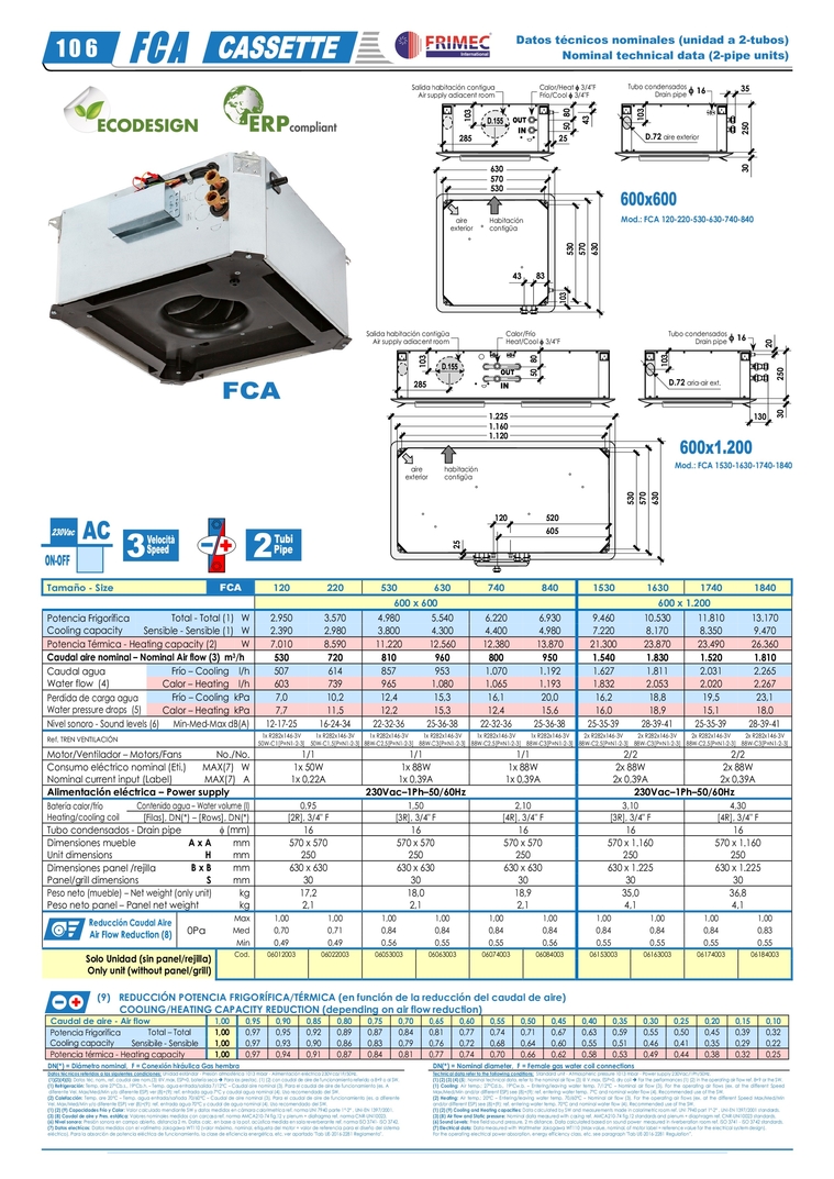
                                                                                           Tamaño - Size  FCA  120  220  530  630  740  840  1530  1630  1740  1840      600 x 600  600 x 1.200  Potencia Frigorífica  Cooling capacity  Total - Total (1)   W  2.950  3.570  4.980  5.540  6.220  6.930  9.460  10.530  11.810  13.170  Sensible - Sensible (1)   W  2.390  2.980  3.800  4.300  4.400  4.980  7.220  8.170  8.350  9.470  Potencia Térmica - Heating capacity (2)  W  7.010  8.590  11.220  12.560  12.380  13.870  21.300  23.870  23.490  26.360  Caudal aire nominal – Nominal Air flow (3)  m 3 /h  530 720 810 960 800 950 1.540  1.830  1.520  1.810  Caudal agua  Water flow  (4)  Frío – Cooling    l/h  507  614  857  953  1.070  1.192  1.627  1.811  2.031  2.265  Calor – Heating    l/h  603  739  965  1.080  1.065  1.193  1.832  2.053  2.020  2.267  Perdida de carga agua  Water pressure drops  (5)  Frío – Cooling  kPa  7,0  10,2  12,4  15,3  16,1  20,0  16,2  18,8  19,5  23,1  Calor – Heating  kPa  7,7  11,5  12,2  15,3  12,4  15,6  16,0  18,9  15,1  18,0  Nivel sonoro - Sound levels (6)     Min-Med-Max  dB(A)  12-17-25 16-24-34 22-32-36 25-36-38 22-32-36 25-36-38 25-35-39 28-39-41 25-35-39 28-39-41  Ref. TREN VENTILACIÓN   1x R282x146-3V  50W-C1[P=N1-2-3]  1x R282x146-3V  50W-C1,5[P=N1-2-3]  1x R282x146-3V  88W-C2,5[P=N1-2-3]  1x R282x146-3V  88W-C3[P=N1-2-3]  1x R282x146-3V  88W-C2,5[P=N1-2-3]  1x R282x146-3V  88W-C3[P=N1-2-3]  2x R282x146-3V  88W-C2,5[P=N1-2-3]  2x R282x146-3V  88W-C3[P=N1-2-3]  2x R282x146-3V  88W-C2,5[P=N1-2-3]  2x R282x146-3V  88W-C3[P=N1-2-3]  Motor/Ventilador – Motors/Fans  No./No.  1/1 1/1 1/1 2/2 2/2  Consumo eléctrico nominal (Eti.)  Nominal current input (Label)  MAX(7)   W  1x 50W  1x 88W  1x 88W  2x 88W  2x 88W  MAX(7)   A  1x 0,22A  1x 0,39A  1x 0,39A  2x 0,39A  2x 0,39A  Alimentación eléctrica – Power supply  230Vac–1Ph–50/60Hz  230Vac–1Ph–50/60Hz  Batería calor/frío Heating/cooling coil  Contenido agua – Water volume (l)  0,95 1,50 2,10 3,10 4,30  [Filas], DN(*) – [Rows], DN(*)   [2R], 3/4" F  [3R], 3/4" F  [4R], 3/4" F  [3R], 3/4" F  [4R], 3/4" F  Tubo condensados - Drain pipe   (mm)  16 16 16 16 16  Dimensiones mueble  Unit dimensions  A x A  mm  570 x 570  570 x 570  570 x 570  570 x 1.160  570 x 1.160  H  mm  250 250 250 250 250  Dimensiones panel /rejilla  Panel/grill dimensions  B x B  mm  630 x 630  630 x 630  630 x 630  630 x 1.225  630 x 1.225   S  mm  30 30 30 30 30  Peso neto (mueble) – Net weight (only unit) kg  17,2 18,0 18,9 35,0 36,8  Peso neto panel – Panel net weight  kg  2,1 2,1  2,1  4,1 4,1    R educción Caudal Aire  Air Flow Reduction (8)  0Pa  Max  1,00 1,00 1,00 1,00 1,00 1,00 1,00 1,00 1,00 1,00  Med  0,70 0,71 0,84 0,84 0,84 0,84 0,84 0,84 0,84 0,83  Min  0,49 0,49 0,56 0,55 0,55 0,56 0,55 0,55 0,55 0,55  Solo Unidad (sin panel/rejilla)  Only unit (without panel/grill)  Cod.  06012003   06022003   06053003   06063003   06074003   06084003   06153003   06163003   06174003   06184003                           (9)   REDUCCIÓN POTENCIA FRIGORÍFICA/TÉRMICA (en función de la reducción del caudal de aire)          COOLING/HEATING CAPACITY REDUCTION (depending on air flow reduction)    Caudal de aire - Air flow  1,00  0,95  0,90  0,85  0,80  0,75  0,70  0,65  0,60  0,55  0,50  0,45  0,40  0,35  0,30  0,25  0,20  0,15  0,10    Potencia Frigorífica   Cooling capacity            Total – Total    1,00  0,97  0,95  0,92  0,89  0,87  0,84  0,81  0,77  0,74  0,71  0,67  0,63  0,59  0,55  0,50  0,45  0,39  0,32    Sensibile - Sensible  1,00  0,97  0,93  0,90  0,86  0,83  0,79  0,76  0,72  0,68  0,64  0,60  0,55  0,51  0,46  0,41  0,35  0,29  0,22    Potencia térmica - Heating capacity  1,00  0,97  0,94  0,91  0,87  0,84  0,81  0,77  0,74  0,70  0,66  0,62  0,58  0,53  0,49  0,44  0,38  0,32  0,25    DN(*) = Diámetro nominal,  F = Conexión hiráulica Gas hembra    DN(*) = Nominal diameter,  F = Female gas water coil connections  Datos técnicos referidos a las siguientes condiciones: Unidad estándar - Presión atmosférica 1013 mbar - Alimentación eléctrica 230Vca/1F/50Hz.   (1)(2)(4)(5): Datos téc. nom., ref. caudal aire nom.(3) @V.max, ESP=0, batería seca  Para las prestac. (1) (2) con caudal de aire de funcionamiento referido a 8+9 o al SW.  (1) Refrigeración: Temp. aire 27°Cb.s., 19°Cb.h. – Temp. agua entrada/salida 7/12°C – Caudal aire nominal (3). Para el caudal de aire de funcionamiento (es. A  diferente Vel. Max/Med/Min y/o diferente ESP) ver (8)+(9): ref. entrada agua 7°C y caudal agua nominal (4). Uso recomendado del SW.  (2) Calefacción: Temp. are 20°C – Temp. agua entrada/sañoda 70/60°C – Caudal de aire nominal (3). Para el caudal de aire de funcionamiento (es. a diferente Vel. Max/Med/Min y/o diferente ESP) ver (8)+(9): ref. entrada agua 70°C y caudal de agua nominal (4). Uso recomendado del SW.  (1) (2) (9) Capacidades Frío y Calor: Valor calculado mendiante SW y datos medidos en cámara calorimetrica ref. norma UNI 7940 parte 1°-2° , UNI-EN 1397/2001. (3) (8) Caudal de aire y Pres. estática: Valores nominales medidos con carcasa ref. norma AMCA210-74 fig.12 y plenum + diafragma ref. norma CNR-UNI10023.        (6) Nivel sonoro: Presión sonora en campo abierto, distancia 2 m. Datos calc. en base a la pot. acústica medida en sala reverberante ref. norma ISO 3741- ISO 3742. (7) Datos electrícos: Datos medidos con el vatímetro Jokogawa WT110 (valor máximo, nominal, etiqueta del motor = valor de referencia para el diseño del sistema  eléctrico). Para la absorción de potencia eléctrica de funcionamiento, la clase de eficiencia energética, etc. ver apartado "Tab UE-2016-2281 Reglamento".    Technical data refer to the following conditions:  Standard unit - Atmospheric pressure 1013 mbar - Power supply 230Vac/1Ph/50Hz. (1) (2) (3) (4) (5): Nominal technical data, refer to the nominal air flow (3) @ V.max, ESP=0, dry coil  For the performances (1) (2) in the operating air flow ref. 8+9 or the SW.  (1) Cooling: Air temp.: 27°Cd.b., 19°Cw.b. – Entering/leaving water temp. 7/12°C – Nominal air flow (3). For the operating air flows (ex. at the different Speed Max/Med/Min and/or different ESP) see (8)+(9): ref. entering water temp. 7°C and nominal water flow (4). Recommended use of the SW.  (2) Heating: Air temp.: 20°C – Entering/leaving water temp. 70/60°C – Nominal air flow (3). For the operating air flows (ex. at the different Speed Max/Med/Min and/or different ESP) see (8)+(9): ref. entering water temp. 70°C and nominal water flow (4). Recommended use of the SW.  (1) (2) (9) Cooling and Heating capacities: Data calculated by SW and measurements made in calorimetric room ref. UNI 7940 part 1°-2° , UNI-EN 1397/2001 standards. (3) (8) Air flow and Static pressure: Nominal data measured with casing ref. AMCA210-74 fig.12 standards and plenum + diaphragm ref. CNR-UNI10023 standards.  (6) Sound Levels: Free field sound pressure, 2 m distance. Data calculated based on sound power  measured in riverberation room ref. ISO 3741 - ISO 3742 standards. (7) Electrical data: Data measured with Wattmeter Jokogawa WT110 (Max value, nominal, of motor label = reference value for the electrical system design).  For the operating electrical power absorption, energy efficiency class, etc. see paragraph "Tab UE-2016-2281 Regulation”.    Datos técnicos nominales (unidad a 2-tubos) Nominal technical data (2-pipe units) 1 0 6   530  570  630  250  30   80   35  Calor/Heat  3/4"F  Frío/Cool  3/4"F  Salida habitación contigua Air supply adiacent room Tubo condensados Drain pipe   16 83  43 50   43   285  10 3  10 3  D.72  aire exterior  530  570  630  103   Habitación  contigüa  aire  exterior  25  530  570  630  250  30   Tubo condensados Drain pipe   16 Calor/Frío  Heat/Cool  3/4"F  Salida habitación contigüa Air supply adiacent room 10 3  D.72  aria-air ext.  habitación  contigüa  aire  exterior  285  10 3  80   50   130  20   25   1.120  1.160  1.225  605  520  120  Mod.: FCA 120-220-530-630-740-840  Mod.: FCA 1530-1630-1740-1840 


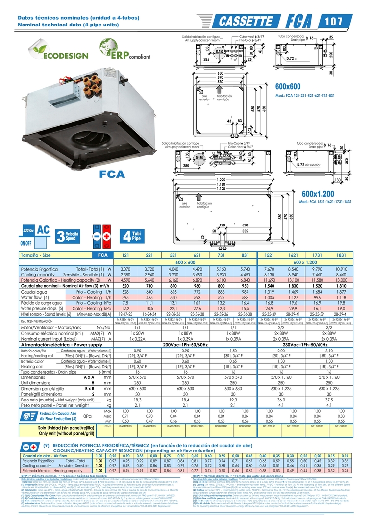
                                                                                        Tamaño - Size  FCA  121  221  521  621  731  831  1521  1621  1731  1831      600 x 600  600 x 1.200  Potencia Frigorífica  Cooling capacity  Total - Total (1)   W  3.070  3.720  4.040  4.490  5.150  5.740  7.670  8.540  9.790  10.910  Sensibile - Sensible (1)   W  2.350  2.940  3.230  3.650  3.930  4.450  6.130  6.940  7.460  8.460  Potencia Calorífica - Heating capacity (2)  W  4.590  5.640  6.160  6.890  6.100  6.840  11.690  13.100  11.580  13.000  Caudal aire nominal – Nominal Air flow (3)  m 3 /h  520 710 810 960 800 950 1.540  1.830  1.520  1.810  Caudal agua  Water flow  (4)  Frío – Cooling    l/h  528  640  695  772  886  987  1.319  1.469  1.684  1.877  Calor – Heating    l/h  395  485  530  593  525  588  1.005  1.127  996  1.118  Pérdida de carga agua  Water pressure drops  (5)  Frío – Cooling  kPa  7,5  11,1  13,1  16,1  13,2  16,4  16,8  19,6  16,9  19,8  Calor – Heating  kPa  12,2  18,5  22,1  27,6  12,3  15,5  24,9  29,9  16,1  19,0  Nivel sonoro - Sound levels (6)      Min-Med-Max  dB(A)  12-17-25 16-24-34 22-32-36 25-36-38 22-32-36 25-36-38 25-35-39 28-39-41 25-35-39 28-39-41  Ref. TREN VENTILACIÓN  1x R282x146-3V  50W-C1[P=N1-2-3]  1x R282x146-3V  50W-C1,5[P=N1-2-3]  1x R282x146-3V  88W-C2,5[P=N1-2-3]  1x R282x146-3V  88W-C3[P=N1-2-3]  1x R282x146-3V  88W-C2,5[P=N1-2-3]  1x R282x146-3V  88W-C3[P=N1-2-3]  2x R282x146-3V  88W-C2,5[P=N1-2-3]  2x R282x146-3V  88W-C3[P=N1-2-3]  2x R282x146-3V  88W-C2,5[P=N1-2-3]  2x R282x146-3V  88W-C3[P=N1-2-3]  Motor/Ventilador – Motors/Fans  No./No.  1/1 1/1 1/1 2/2 2/2  Consumo eléctrico nominal (Eti.)  Nominal current input (Label)  MAX(7)   W  1x 50W  1x 88W  1x 88W  2x 88W  2x 88W  MAX(7)   A  1x 0,22A  1x 0,39A  1x 0,39A  2x 0,39A  2x 0,39A  Alimentación eléctrica – Power supply  230Vac–1Ph–50/60Hz  230Vac–1Ph–50/60Hz  Batería calor/frío  Heating/cooling coil  Contenido agua – Water volume (l)  0,95 0,95 1,50 2,00 3,10  [Filas], DN(*) – [Rows], DN(*)    [2R], 3/4" F  [2R], 3/4" F  [3R], 3/4" F  [2R], 3/4" F  [3R], 3/4" F  Batería calor Heating coil  Contenido agua – Water volume (l)  0,60 0,60 0,65 1,30 1,30  [Filas], DN(*) – [Rows], DN(*)    [1R], 3/4" F  [1R], 3/4" F  [1R], 3/4" F  [1R], 3/4" F  [1R], 3/4" F  Tubo condensados - Drain pipe   (mm)  16 16   16   16   16   Dimensiones  Unit dimensions  A x A  mm  570 x 570  570 x 570  570 x 570  570 x 1.160  570 x 1.160  H  mm  250 250 250 250 250  Dimensión panel/rejilla  Panel/grill dimensions  B x B  mm  630 x 630  630 x 630  630 x 630  630 x 1.225  630 x 1.225   S  mm  30 30 30 30 30  Peso neto (mueble) – Net weight (only unit) kg  18,3 18,4 19,3 36,0 37,5  Peso neto panel – Panel net weight  kg  2,1 2,1  2,1  4,1 4,1    Reducción Caudal Aire  Air Flow Reduction (8)   0Pa  Max  1,00 1,00 1,00 1,00 1,00 1,00 1,00 1,00 1,00 1,00  Med  0,71 0,70 0,84 0,84 0,84 0,84 0,84 0,84 0,84 0,83  Min  0,50 0,49 0,56 0,55 0,55 0,56 0,55 0,55 0,55 0,55  Solo Unidad (sin panel/rejilla)  Only unit (without panel/grill)  Cod.  06012103   06022103   06052103   06062103   06073103   06083103   06152103   06162103   06173103   06183103                           (9)   REDUCCIÓN POTENCIA FRIGORÍFICA/TÉRMICA (en función de la reducción del caudal de aire)          COOLING/HEATING CAPACITY REDUCTION (depending on air flow reduction)    Caudal de aire - Air flow  1,00  0,95  0,90  0,85  0,80  0,75  0,70  0,65  0,60  0,55  0,50  0,45  0,40  0,35  0,30  0,25  0,20  0,15  0,10    Potencia Frigorífica   Cooling capacity            Total – Total    1,00  0,97  0,95  0,92  0,89  0,87  0,84  0,81  0,77  0,74  0,71  0,67  0,63  0,59  0,55  0,50  0,45  0,39  0,32    Sensibile - Sensible  1,00  0,97  0,93  0,90  0,86  0,83  0,79  0,76  0,72  0,68  0,64  0,60  0,55  0,51  0,46  0,41  0,35  0,29  0,22    Potencia térmica - Heating capacity  1,00  0,97  0,94  0,91  0,87  0,84  0,81  0,77  0,74  0,70  0,66  0,62  0,58  0,53  0,49  0,44  0,38  0,32  0,25    DN(*) = Diámetro nominal,  F = Conexión hiráulica Gas hembra    DN(*) = Nominal diameter,  F = Female gas water coil connections  Datos técnicos referidos a las siguientes condiciones: Unidad estándar - Presión atmosférica 1013 mbar - Alimentación eléctrica 230Vca/1F/50Hz.    (1)(2)(4)(5): Datos téc. nom., ref. caudal aire nom.(3) @V.max, ESP=0, batería seca  Para las prestac. (1) (2) con caudal de aire de funcionamiento referido a 8+9 o al SW. (1) Refrigeración: Temp. aire 27°Cb.s., 19°Cb.h. – Temp. agua entrada/salida 7/12°C – Caudal aire nominal (3). Para el caudal de aire de funcionamiento (es. A   diferente Vel. Max/Med/Min y/o diferente ESP) ver (8)+(9): ref. entrada agua 7°C y caudal agua nominal (4). Uso recomendado del SW. (2) Calefacción: Temp. are 20°C – Temp. agua entrada/sañoda 70/60°C – Caudal de aire nominal (3). Para el caudal de aire de funcionamiento (es. a diferente  Vel. Max/Med/Min y/o diferente ESP) ver (8)+(9): ref. entrada agua 70°C y caudal de agua nominal (4). Uso recomendado del SW. (1) (2) (9) Capacidades Frío y Calor: Valor calculado mendiante SW y datos medidos en cámara calorimetrica ref. norma UNI 7940 parte 1°-2° , UNI-EN 1397/2001.  (3) (8) Caudal de aire y Pres. estática: Valores nominales medidos con carcasa ref. norma AMCA210-74 fig.12 y plenum + diafragma ref. norma CNR-UNI10023.       (6) Nivel sonoro: Presión sonora en campo abierto, distancia 2 m. Datos calc. en base a la pot. acústica medida en sala reverberante ref. norma ISO 3741- ISO 3742.  (7) Datos electrícos: Datos medidos con el vatímetro Jokogawa WT110 (valor máximo, nominal, etiqueta del motor = valor de referencia para el diseño del sistema eléctrico). Para la absorción de potencia eléctrica de funcionamiento, la clase de eficiencia energética, etc. ver apartado "Tab UE-2016-2281 Reglamento".    Technical data refer to the following conditions:  Standard unit - Atmospheric pressure 1013 mbar - Power supply 230Vac/1Ph/50Hz.  (1) (2) (3) (4) (5): Nominal technical data, refer to the nominal air flow (3) @ V.max, ESP=0, dry coil  For the performances (1) (2) in the operating air flow ref. 8+9 or the SW. (1) Cooling: Air temp.: 27°Cd.b., 19°Cw.b. – Entering/leaving water temp. 7/12°C – Nominal air flow (3). For the operating air flows (ex. at the different Speed  Max/Med/Min and/or different ESP) see (8)+(9): ref. entering water temp. 7°C and nominal water flow (4). Recommended use of the SW. (2) Heating: Air temp.: 20°C – Entering/leaving water temp. 70/60°C – Nominal air flow (3). For the operating air flows (ex. at the different Speed Max/Med/Min  and/or different ESP) see (8)+(9): ref. entering water temp. 70°C and nominal water flow (4). Recommended use of the SW. (1) (2) (9) Cooling and Heating capacities: Data calculated by SW and measurements made in calorimetric room ref. UNI 7940 part 1°-2° , UNI-EN 1397/2001 standards.  (3) (8) Air flow and Static pressure: Nominal data measured with casing ref. AMCA210-74 fig.12 standards and plenum + diaphragm ref. CNR-UNI10023 standards. (6) Sound Levels: Free field sound pressure, 2 m distance. Data calculated based on sound power  measured in riverberation room ref. ISO 3741 - ISO 3742 standards.  (7) Electrical data: Data measured with Wattmeter Jokogawa WT110 (Max value, nominal, of motor label = reference value for the electrical system design). For the operating electrical power absorption, energy efficiency class, etc. see paragraph "Tab UE-2016-2281 Regulation”.    Datos técnicos nominales (unidad a 4-tubos) Nominal technical data (4-pipe units)  1 0 7 530  570  630  250  30   80   35  Calor-Heat  3/4"F  Frío-Cool  3/4"F  Salida habitación contigua Air supply adiacent room Tubo condensados  Drain pipe   16 83  43 50   43   285  10 3  10 3  D.72  c  530  570  630  103   habitación  contigüa  aire  exterior  25  530  570  630  250  30   Tubo condensados Drain pipe   16 Frío-Cool  3/4"F  Calor-Heat  3/4"F  Salida habitación contigüa Air supply adiacent room 10 3  D.72  airr exterior  habitación  contigüa  aire  exterior  285  10 3  50   50   80   50   130  20   25   1.120  1.160  1.225  555  50  520  120  Mod.: FCA 121-221-521-621-731-831  Mod.: FCA 1521-1621-1731-1831 


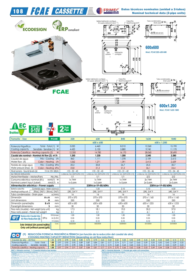
                                                                                          Tamaño - Size  FCAE  220  630  840  1630  1840      600 x 600  600 x 1.200  Potencia Frigorífica  Cooling capacity  Total - Total (1)   W  5.020  6.460  8.010  12.260  15.190  Sensibile - Sensible (1)   W  4.420  5.130  5.880  9.740  11.170  Potencia Calorifica - Heating capacity (2)  W  12.350  14.780  16.170  28.060  30.690  Caudal aire nominal – Nominal Air flow (3)  m 3 /h  1.250 1.230 1.200 2.340 2.280  Caudal de agua  Water flow  (4)  Frío – Cooling    l/h  863  1.111  1.378  2.109  2.613  Calor – Heating    l/h  1.062  1.271  1.391  2.413  2.639  Perdida de carga agua  Water pressure drops  (5)  Frío – Cooling  kPa  20,2  20,8  26,7  25,5  30,7  Calor – Heating  kPa  23,8  21,2  21,2  26,1  24,4  Nivel sonoro - Sound levels (6)     1V-M-10V dB(A)  <10 – 32 – 43  <10 – 32 – 43  <10 – 31 – 42  <10 – 35 – 46  <10 – 34 – 45  Ref. TREN DE VENTILACIÓN   1x R282x146, 74W,  [SWP=N/FIX.1/10]   1x R282x146, 74W,  [SWP=N/FIX.1/10]   1x R282x146, 74W,  [SWP=N/FIX.1/10]   1x R282x146, 74W,  [SWP=N/FIX.1/10]  1x  R282x146,  74W,  [SWP=N/FIX.1/10]   Motor/Ventilador – Motors/Fans  No./No.  1/1 1/1 1/1 2/2 2/2  Consumo eléctrico nominal (Eti.)  Nominal current input (Label)  MAX(7)   W  1x 74W  1x 74W  1x 74W  2x 74W  2x 74W  MAX(7)   A  1x 0,64A  1x 0,64A  1x 0,64A  2x 0,64A  2x 0,64A  Alimentación eléctrica – Power supply  230Vca–1F–50/60Hz  230Vca–1F–50/60Hz  Batería calor/frío  Heating/cooling coil  Contenido agua – Water volume (l)  0,95 1,50 2,10 3,10 4,30  [Filas], DN(*) – [Rows], DN(*)   [2R], 3/4" F  [3R], 3/4" F  [4R], 3/4" F  [3R], 3/4" F  [4R], 3/4" F  Tubo condensados - Drain pipe   (mm)  16 16 16 16 16  Dimensión  Unit dimensions  A x A  mm  570 x 570  570 x 570  570 x 570  570 x 1.160  570 x 1.160  H  mm  250 250 250 250 250  Dimensión panel/rejilla  Panel/grill dimensions  B x B  mm  630 x 630  630 x 630  630 x 630  630 x 1.225  630 x 1.225   S  mm  30 30 30 30 30  Peso neto (mueble) – Net weight (only unit) kg  17,3 18,1 19,0 35,2 37,0  Peso neto panel – Panel net weight  kg  2,1 2,1  2,1  4,1 4,1    Reducción Caudal Aire  Air Flow Reduction (8)  0Pa  10V(max)  1,00 1,00 1,00 1,00 1,00  M  (5,5V)  0,55 0,55 0,55 0,55 0,55  1V  (min)  0,10 0,10 0,10 0,10 0,10  Solo Unidad (sin panel/rejilla)  Only unit (without panel/grill)  Cod.  06022004   06063004   06084004   06163004   06184004                 (9)   REDUCCIÓN POTENCIA FRIGORÍFICA/TÉRMICA (en función de la reducción del caudal de aire)          COOLING/HEATING CAPACITY REDUCTION (depending on air flow reduction)    Caudal de aire - Air flow   1,00  0,95  0,90  0,85  0,80  0,75  0,70  0,65  0,60  0,55  0,50  0,45  0,40  0,35  0,30  0,25  0,20  0,15  0,10    Potencia Frigorífica    Cooling capacity            Total – Total    1,00  0,97  0,95  0,92  0,89  0,87  0,84  0,81  0,77  0,74  0,71  0,67  0,63  0,59  0,55  0,50  0,45  0,39  0,32    Sensibile - Sensible  1,00  0,97  0,93  0,90  0,86  0,83  0,79  0,76  0,72  0,68  0,64  0,60  0,55  0,51  0,46  0,41  0,35  0,29  0,22    Potencia calorífica - Heating capacity  1,00  0,97  0,94  0,91  0,87  0,84  0,81  0,77  0,74  0,70  0,66  0,62  0,58  0,53  0,49  0,44  0,38  0,32  0,25    DN(*) = Diámetro nominal,  F = Conexión hiráulica Gas hembra    DN(*) = Nominal diameter,  F = Female gas water coil connections  Datos técnicos referidos a las siguientes condiciones: Unidad estándar - Presión atmosférica 1013 mbar - Alimentación eléctrica 230Vca/1F/50Hz.   (1)(2)(4)(5): Datos téc. nom., ref. caudal aire nom.(3) @V.max, ESP=0, batería seca  Para las prestac. (1) (2) con caudal de aire de funcionamiento referido a 8+9 o al SW.  (1) Refrigeración: Temp. aire 27°Cb.s., 19°Cb.h. – Temp. agua entrada/salida 7/12°C – Caudal aire nominal (3). Para el caudal de aire de funcionamiento (es. A  diferente Vel. Max/Med/Min y/o diferente ESP) ver (8)+(9): ref. entrada agua 7°C y caudal agua nominal (4). Uso recomendado del SW.  (2) Calefacción: Temp. are 20°C – Temp. agua entrada/sañoda 70/60°C – Caudal de aire nominal (3). Para el caudal de aire de funcionamiento (es. a diferente Vel. Max/Med/Min y/o diferente ESP) ver (8)+(9): ref. entrada agua 70°C y caudal de agua nominal (4). Uso recomendado del SW.  (1) (2) (9) Capacidades Frío y Calor: Valor calculado mendiante SW y datos medidos en cámara calorimetrica ref. norma UNI 7940 parte 1°-2° , UNI-EN 1397/2001. (3) (8) Caudal de aire y Pres. estática: Valores nominales medidos con carcasa ref. norma AMCA210-74 fig.12 y plenum + diafragma ref. norma CNR-UNI10023.       (6) Nivel sonoro: Presión sonora en campo abierto, distancia 2 m. Datos calc. en base a la pot. acústica medida en sala reverberante ref. norma ISO 3741- ISO 3742.  (7) Datos electrícos: Datos medidos con el vatímetro Jokogawa WT110 (valor máximo, nominal, etiqueta del motor = valor de referencia para el diseño del sistema eléctrico). Para la absorción de potencia eléctrica de funcionamiento, la clase de eficiencia energética, etc. ver apartado "Tab UE-2016-2281 Reglamento".    Technical data refer to the following conditions:  Standard unit - Atmospheric pressure 1013 mbar - Power supply 230Vac/1Ph/50Hz. (1) (2) (3) (4) (5): Nominal technical data, refer to the nominal air flow (3) @ V.max=10V, ESP=0, dry coil  For the performances (1) (2) in the operating air flow ref. 8+9 or the SW.  (1) Cooling: Air temp.: 27°Cd.b., 19°Cw.b. – Entering/leaving water temp. 7/12°C – Nominal air flow (3). For the operating air flows (ex. at the different Speed, Signals, ESP) see (8)+(9): ref. entering water temp. 7°C and nominal water flow (4). Recommended use of the SW.  (2) Heating: Air temp.: 20°C – Entering/leaving water temp. 70/60°C – Nominal air flow (3). For the operating air flows (ex. at the different Speed, Signals, ESP) see (8)+(9): ref. entering water temp. 70°C and nominal water flow (4). Recommended use of the SW.  (1) (2) (9) Cooling and Heating capacities: Data calculated by SW and measurements made in calorimetric room ref. UNI 7940 part 1°-2° , UNI-EN 1397/2001 standards. (3) (8) Air flow and Static pressure: Nominal data measured with casing ref. AMCA210-74 fig.12 standards and plenum + diaphragm ref. CNR-UNI10023 standards. (6) Sound Levels: Free field sound pressure, 2 m distance. Data calculated based on sound power  measured in riverberation room ref. ISO 3741 - ISO 3742 standards.  (7) Electrical data: Data measured with Wattmeter Jokogawa WT110 (Max value, nominal, of motor label = reference value for the electrical system design). For the operating electrical power absorption, energy efficiency class, etc. see paragraph "Tab UE-2016-2281 Regulation”.    Datos técnicos nominales (unidad a 2-tubos) Nominal technical data (2-pipe units) 1 0 8   530  570  630  250  30   80   35  Calor/Frío  Heat/Cool  3/4"F  Salida habitación contigua Air supply adiacent room Tubo condensados  Drain pipe   16 83  43 50   43   285  10 3  10 3  D.72  aria-air ext.  530  570  630  103   habitación  contigüa  aire  exterior  25  530  570  630  250  30   Tubo condensados  Drain pipe   16 Calor/Frío  Heat/Cool  3/4"F  Salida habitación contigüa Air supply adiacent room 10 3  D.72  aire exterior  habitación  contigüa  aire  exterior  285  10 3  80   50   130  20   25   1.120  1.160  1.225  605  520  120  Mod.: FCAE 220-630-840  Mod.: FCAE 1630-1840 


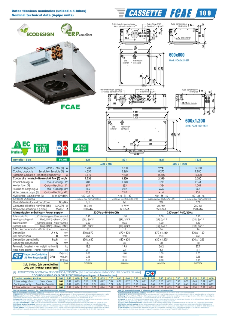
                                                                                            Tamaño - Size  FCAE  621  831  1621  1831      600 x 600  600 x 1.200  Potencia Frigorífica  Cooling capacity  Totale - Total (1)   W  5.230  6.630  9.940  12.580  Sensibile - Sensible (1)   W  4.350  5.260  8.270  9.980  Potencia Calorifica - Heating capacity (2)  W  8.110  7.970  15.400  15.130  Caudal aire nominal – Nominal Air flow (3)  m 3 /h  1.230 1.200 2.340 2.280  Caudal de agua  Water flow  (4)  Frío – Cooling    l/h  900  1.140  1.710  2.164  Calor – Heating    l/h  697  685  1.324  1.301  Perdida de carga agua  Water pressure drops  (5)  Frío – Cooling  kPa  21,9  21,9  26,5  26,4  Calor – Heating  kPa  38,2  21,0  41,4  25,7  Nivel sonoro - Sound levels (6)    1V-M-10V dB(A)  <10 – 32 – 43  <10 – 31 – 42  <10 – 35 – 46  <10 – 34 – 45  Ref. TREN DE VENTILACIÓN  1x R282x146, 74W,  [SWP=N/FIX.1/10]   1x R282x146, 74W,  [SWP=N/FIX.1/10]   1x R282x146, 74W,  [SWP=N/FIX.1/10]   1x R282x146, 74W,  [SWP=N/FIX.1/10]   Motor/Ventilador – Motors/Fans  No./No.  1/1 1/1 2/2 2/2  Consumo eléctrico nominal (Eti.)  Nominal current input (Label)  MAX(7)   W  1x 74W  1x 74W  2x 74W  2x 74W  MAX(7)   A  1x 0,64A  1x 0,64A  2x 0,64A  2x 0,64A  Alimentación eléctrica – Power supply  230Vca–1F–50/60Hz  230Vca–1F–50/60Hz  Batería calor/frío Heating/cooling coil  Contenido agua – Water volume (l)  0,95 1,50 2,00 3,10  [Filas], DN(*) – [Rows], DN(*)    [2R], 3/4" F  [3R], 3/4" F  [2R], 3/4" F  [3R], 3/4" F  Batería calor Heating coil  Contenido agua – Water volume (l)  0,60 0,65 1,30 1,30  [Filas], DN(*) – [Rows], DN(*)    [1R], 3/4" F  [1R], 3/4" F  [1R], 3/4" F  [1R], 3/4" F  Tubo de condensados - Drain pipe   (mm)  16   16   16   16   Dimensión  Unit dimensions  A x A  mm  570 x 570  570 x 570  570 x 1.160  570 x 1.160  H  mm  250 250 250 250  Dimensión panel/rejilla  Panel/grill dimensions  B x B  mm  630 x 630  630 x 630  630 x 1.225  630 x 1.225   S  mm  30 30 30 30  Peso neto (mueble) – Net weight (only unit) kg  18,5 19,4 36,2 37,7  Peso neto panel – Panel net weight  kg  2,1  2,1  4,1 4,1    Reducción Caudal Aire  Air Flow Reduction (8)  0Pa  10V(max)  1,00 1,00 1,00 1,00  M  (5,5V)  0,55 0,55 0,55 0,55  1V  (min)  0,10 0,10 0,10 0,10  Solo Unidad (sin panel/rejilla)  Only unit (without panel/grill)  Cod.  06062104   06083104   06162104   06183104             (9)    REDUCCIÓN POTENCIA FRIGORÍFICA/TÉRMICA (en función de la reducción del caudal de aire)           COOLING/HEATING CAPACITY REDUCTION (depending on air flow reduction)    Caudal de aire - Air flow   1,00  0,95  0,90  0,85  0,80  0,75  0,70  0,65  0,60  0,55  0,50  0,45  0,40  0,35  0,30  0,25  0,20  0,15  0,10    Potencia Frigorífica   Cooling capacity            Total – Total    1,00  0,97  0,95  0,92  0,89  0,87  0,84  0,81  0,77  0,74  0,71  0,67  0,63  0,59  0,55  0,50  0,45  0,39  0,32    Sensibile - Sensible  1,00  0,97  0,93  0,90  0,86  0,83  0,79  0,76  0,72  0,68  0,64  0,60  0,55  0,51  0,46  0,41  0,35  0,29  0,22    Potencia térmica - Heating capacity  1,00  0,97  0,94  0,91  0,87  0,84  0,81  0,77  0,74  0,70  0,66  0,62  0,58  0,53  0,49  0,44  0,38  0,32  0,25    DN(*) = Diámetro nominal,  F = Conexión hiráulica Gas hembra    DN(*) = Nominal diameter,  F = Female gas water coil connections  Datos técnicos referidos a las siguientes condiciones: Unidad estándar - Presión atmosférica 1013 mbar - Alimentación eléctrica 230Vca/1F/50Hz.    (1)(2)(4)(5): Datos téc. nom., ref. caudal aire nom.(3) @V.max, ESP=0, batería seca  Para las prestac. (1) (2) con caudal de aire de funcionamiento referido a 8+9 o al SW. (1) Refrigeración: Temp. aire 27°Cb.s., 19°Cb.h. – Temp. agua entrada/salida 7/12°C – Caudal aire nominal (3). Para el caudal de aire de funcionamiento (es. A   diferente Vel. Max/Med/Min y/o diferente ESP) ver (8)+(9): ref. entrada agua 7°C y caudal agua nominal (4). Uso recomendado del SW. (2) Calefacción: Temp. are 20°C – Temp. agua entrada/sañoda 70/60°C – Caudal de aire nominal (3). Para el caudal de aire de funcionamiento (es. a diferente  Vel. Max/Med/Min y/o diferente ESP) ver (8)+(9): ref. entrada agua 70°C y caudal de agua nominal (4). Uso recomendado del SW. (1) (2) (9) Capacidades Frío y Calor: Valor calculado mendiante SW y datos medidos en cámara calorimetrica ref. norma UNI 7940 parte 1°-2° , UNI-EN 1397/2001.  (3) (8) Caudal de aire y Pres. estática: Valores nominales medidos con carcasa ref. norma AMCA210-74 fig.12 y plenum + diafragma ref. norma CNR-UNI10023.       (6) Nivel sonoro: Presión sonora en campo abierto, distancia 2 m. Datos calc. en base a la pot. acústica medida en sala reverberante ref. norma ISO 3741- ISO 3742.  (7) Datos electrícos: Datos medidos con el vatímetro Jokogawa WT110 (valor máximo, nominal, etiqueta del motor = valor de referencia para el diseño del sistema eléctrico). Para la absorción de potencia eléctrica de funcionamiento, la clase de eficiencia energética, etc. ver apartado "Tab UE-2016-2281 Reglamento".    Technical data refer to the following conditions:  Standard unit - Atmospheric pressure 1013 mbar - Power supply 230Vac/1Ph/50Hz.  (1) (2) (3) (4) (5): Nominal technical data, refer to the nominal air flow (3) @ V.max=10V, ESP=0, dry coil  For the performances (1) (2) in the operating air flow ref. 8+9 or the SW. (1) Cooling: Air temp.: 27°Cd.b., 19°Cw.b. – Entering/leaving water temp. 7/12°C – Nominal air flow (3). For the operating air flows (ex. at the different Speed, Signals,  ESP) see (8)+(9): ref. entering water temp. 7°C and nominal water flow (4). Recommended use of the SW. (2) Heating: Air temp.: 20°C – Entering/leaving water temp. 70/60°C – Nominal air flow (3). For the operating air flows (ex. at the different Speed, Signals, ESP) see  (8)+(9): ref. entering water temp. 70°C and nominal water flow (4). Recommended use of the SW. (1) (2) (9) Cooling and Heating capacities: Data calculated by SW and measurements made in calorimetric room ref. UNI 7940 part 1°-2° , UNI-EN 1397/2001 standards.  (3) (8) Air flow and Static pressure: Nominal data measured with casing ref. AMCA210-74 fig.12 standards and plenum + diaphragm ref. CNR-UNI10023 standards. (6) Sound Levels: Free field sound pressure, 2 m distance. Data calculated based on sound power  measured in riverberation room ref. ISO 3741 - ISO 3742 standards.  (7) Electrical data: Data measured with Wattmeter Jokogawa WT110 (Max value, nominal, of motor label = reference value for the electrical system design). For the operating electrical power absorption, energy efficiency class, etc. see paragraph "Tab UE-2016-2281 Regulation”.    Datos técnicos nominales (unidad a 4-tubos) Nominal technical data (4-pipe units)  1 0 9 530  570  630  250  30   80   35  Calor-Frío  3/4"F  Freddo-Cool  3/4"F  Salida habitación contigüa Air supply adiacent room Tubo condensados Drain pipe   16 83  43 50   43   285  10 3  10 3  D.72  aire exterior  530  570  630  103   habitación  contigüa  aire  exterior  25  530  570  630  250  30   Tubo condensados Drain pipe   16 Frío-Cool  3/4"F  Calor-Heat  3/4"F  Salida habitación contigüa Air supply adiacent room 10 3  D.72  aire exterior  habitación  contigüa  aire  exterior  285  10 3  50   50   80   50   130  20   25   1.120  1.160  1.225  555  50  520  120  Mod.: FCAE 621-831  Mod.: FCAE 1621-1831 


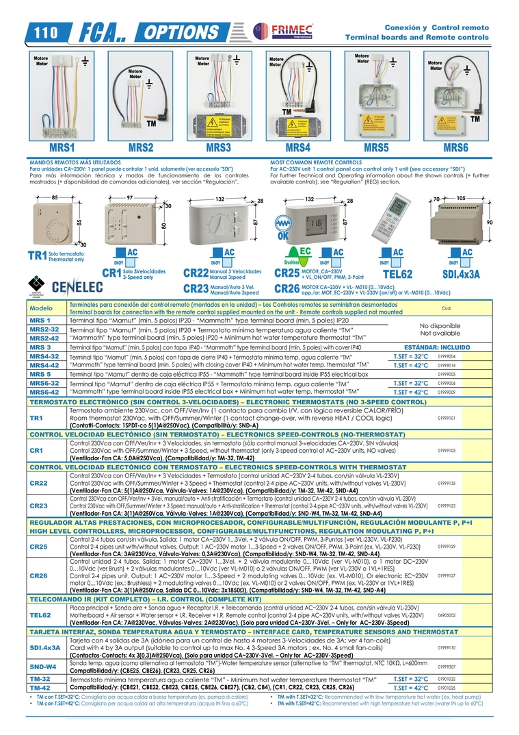
                                     MANDOS REMOTOS MÁS UTILIZADOS Para unidades CA~230V: 1 panel puede controlar 1 unid. solamente (ver accesorio "SDI")  Para más información técnica y modos de funcionamiento de los controles mostrados (+ disponibilidad de comandos adicionales), ver sección “Regulación”.    MOST COMMON REMOTE CONTROLS For AC~230V unit: 1 control panel can control only 1 unit (see accessory “SDI”)  For further Technical and Operating information about the shown controls (+ further available controls), see “Regulation” (REG) section.                                 Modelo  Terminales para conexión del control remoto (montados en la unidad) – Los Controles remotos se suministran desmontados  Terminal boards for connection with the remote control supplied mounted on the unit - Remote controls supplied not mounted  Cod.    MRS 1  Terminal tipo “Mamut” (min. 5 polos) IP20 - “Mammoth” type terminal board (min. 5 poles) IP20   No disponible  Not available   MRS2-32  Terminal tipo “Mamut” (min. 5 polos) IP20 + Termostato mínima temperatura agua caliente “TM”  “Mammoth” type terminal board (min. 5 poles) IP20 + Minimum hot water temperature thermostat “TM”  MRS2-42 MRS 3  Terminal tipo “Mamut” (min. 5 polos) con tapa  IP40 - “Mammoth” type terminal board (min. 5 poles) with cover IP40  ESTÁNDAR: INCLUIDO   MRS4-32  Terminal tipo “Mamut” (min. 5 polos) con tapa de cierre IP40 + Termostato mínima temp. agua caliente “TM”  “Mammoth” type terminal board (min. 5 poles) with closing cover IP40 + Minimum hot water temp. thermostat “TM”  T.SET = 32°C  01999004    MRS4-42  T.SET = 42°C  01999014    MRS 5  Terminal tipo “Mamut” dentro de caja eléctrica IP55 - “Mammoth” type terminal board inside IP55 electrical box    01999005    MRS6-32  Terminal tipo “Mamut” dentro de caja eléctrica IP55 + Termostato mínima temp. agua caliente “TM”  “Mammoth” type terminal board inside IP55 electrical box + Minimum hot water temp. thermostat “TM”  T.SET = 32°C  01999006    MRS6-42  T.SET = 42°C  01999009    TERMOSTATO ELECTRÓNICO (SIN CONTROL 3-VELOCIDADES) – ELECTRONIC THERMOSTATS (NO 3-SPEED CONTROL)  TR1  Termostato ambiente 230Vac, con OFF/Ver/Inv (1 contacto para cambio I/V, con lógica reversible CALOR/FRÍO)  Room thermostat 230Vac, with OFF/Summer/Winter (1 contact change-over, with reverse HEAT / COOL logic)  (Contatti-Contacts: 1SPDT-co 5(1)A@250Vac), (Compatibilità/y: SND-A)  01999101          CONTROL VELOCIDAD ELECTÓNICO (SIN TERMOSTATO) – ELECTRONICS SPEED-CONTROLS (NO-THERMOSTAT)  CR1  Control 230Vca con OFF/Ver/Inv + 3 Velocidades, sin termostato (sólo control manual 3-velocidades CA~230V, SIN válvulas)  Control 230Vac with OFF/Summer/Winter + 3 Speed, without thermostat (only 3-speed control of AC~230V units, NO valves)  (Ventilador-Fan CA: 5,0A@250Vca), (Compatibilidad/y: TM-32, TM-42)  01999103    CONTROL VELOCIDAD ELECTÓNICO CON TERMOSTATO – ELECTRONICS SPEED-CONTROLS WITH THERMOSTAT  CR22  Control 230Vca con OFF/Ver/Inv + 3 Velocidades + Termostato (control unidad AC~230V 2-4 tubos, con/sin válvula VL-230V)  Control 230Vac with OFF/Summer/Winter + 3 Speed + Thermostat (control 2-4 pipe AC~230V units, with/without valves VL-230V)  (Ventilador-Fan CA: 5(1)A@250Vca, Válvula-Valves: 1A@230Vca), (Compatibilidad/y: TM-32, TM-42, SND-A4)  01999135    CR23  Control 230Vca con OFF/Ver/Inv + 3Vel. manual/auto + Anti-stratificación + Termostato (control unidad CA~230V 2-4 tubos, con/sin válvula VL-230V)  Control 230Vac with OFF/Summer/Winter + 3 Speed manual/auto + Anti-stratification + Thermostat (control 2-4 pipe AC~230V units, with/without valves VL-230V)  (Ventilador-Fan CA: 3(1)A@250Vca, Válvula-Valves: 1A@230Vca), (Compatibilidad/y: SND-W4, TM-32, TM-42, SND-A4)  01999123      REGULADOR ALTAS PRESTACIONES, CON MICROPROCESADOR, CONFIGURABLE/MULTIFUNCIÓN, REGULACIÓN MODULANTE P, P+I HIGH LEVEL CONTROLLERS, MICROPROCESSOR, CONFIGURABLE/MULTIFUNCTIONS, REGULATION MODULATING P, P+I  CR25  Control 2-4 tubos con/sin válvula. Salida: 1 motor CA~230V 1...3Vel. + 2 válvula ON/OFF, PWM, 3-Puntos (ver VL-230V, VL-F230)  Control 2-4 pipes unit with/without valves. Output: 1 AC~230V motor 1...3-Speed + 2 valves ON/OFF, PWM, 3-Point (ex. VL-230V, VL-F230)  (Ventilador-Fan CA: 3A@230Vca, Válvula-Valves: 0,3A@230Vca), (Compatibilidad/y: SND-W4, TM-32, TM-42, SND-A4)  01999129    CR26  Control unidad 2-4 tubos. Salida: 1 motor CA~230V 1...3Vel. + 2 válvula modulante 0…10Vdc (ver  VL-M010), o 1 motor DC~230V  0…10Vdc (ver Brush) + 2 válvulas modulantes 0…10Vdc (ver VL-M010) o 2 válvulas ON/OFF, PWM (ver VL-230V o 1VL+1RES)  Control 2-4 pipes unit. Output: 1 AC~230V motor 1…3-Speed + 2 modulating valves 0…10Vdc (ex. VL-M010), Or electronic EC~230V  motor 0…10Vdc (ex.: Brushless) + 2 modulating valves 0…10Vdc (ex. VL-M010) or 2 valves ON/OFF, PWM (ex. VL-230V or 1VL+1RES)  (Ventilador-Fan CA: 3(1)A@250Vca, Salida DC 0...10Vdc: 3x1850Ω), (Compatibilidad/y: SND-W4, TM-32, TM-42, SND-A4)  01999127    TELECOMANDO IR (KIT COMPLETO) – I.R. CONTROL (COMPLETE KIT)  TEL62  Placa principal + Sonda aire + Sonda agua + Receptor I.R. + Telecomando (control unidad AC~230V 2-4 tubos, con/sin válvula VL-230V)  Motherboard + Air sensor + Water sensor + I.R. Receiver + I.R. Remote control (control 2-4 pipe AC~230V units, with/without valves VL-230V)  (Ventilador-Fan CA: 7A@230Vac, Válvulas-Valves: 2A@230Vac), (Solo para unidad CA~230V-3Vel. – Only for  AC~230V-3Speed)  06905002    TARJETA INTERFAZ, SONDA TEMPERATURA AGUA Y TERMOSTATO – INTERFACE CARD, TEMPERATURE SENSORS AND THERMOSTAT  SDI.4x3A  Tarjeta con 4 salidas de 3A (idónea para un control de hasta 4 motores 3-Velocidades de 3A; ver 4 fan-coils)  Card with 4 by 3A output (suitable to control up to max No. 4 3-Speed 3A motors ; ex. No. 4 small fan-coils)  (Contactos-Contacts: 4x 3(0,3)A@250Vca), (Solo para unidad CA~230V-3Vel. – Only for  AC~230V-3Speed)  01999110    SND-W4  Sonda temp. agua (como alternativa al termostato “TM”)-Water temperature sensor (alternative to “TM” thermostat. NTC 10KΩ, L=600mm  Compatibilidad/y: (CBE25, CBE26), (CR23, CR25, CR26)  01999307    TM-32  Termostato mínima temperatura agua caliente “TM” - Minimum hot water temperature thermostat “TM”  Compatibilidad/y: (CBE21, CBE22, CBE23, CBE25, CBE26, CBE27), (CB2, CB4), (CR1, CR22, CR23, CR25, CR26)  T.SET = 32°C  01901022    TM-42  T.SET = 42°C  01901025         TM con T.SET=32°C: Consigliato per acqua calda a bassa temperatura (es. pompa di calore)     TM con T.SET=42°C: Consigliato per acqua calda ad alta temperatura (acqua IN fino a 60°C)       TM with T.SET=32°C: Recommended with low temperature hot water (ex. heat pump)   TM with T.SET=42°C: Recommended with high temperature hot water (water IN up to 60°C)    Conexión y  Control remoto Terminal boards and Remote controls 1 1 0   Solo termostato  Thermostat only  Solo 3Velocidades  3-Speed only  Manual 3 Velocidades  Manual 3speed  Manual/Auto 3 Vel.  Manual/Auto 3speed  MOTOR_CA~230V  + VL_ON/OFF, PWM, 3-Point  MOTOR CA~230V + VL- M010 (0…10Vdc)   opp./or: MOT_EC~230V + VL-230V (on/off) or VL-M010 (0…10Vdc)  30  85   85  97  30  80   132  87   28  132  87   28  105  70  90 


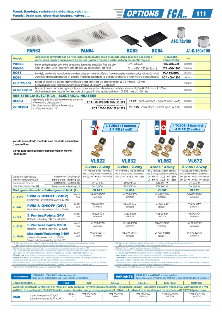
                              Modelo  Accesorios suministados no montados en la unidad (solo montados bajo solicitud específica)  Accessories supplied not mounted on the unit (supplied mounted on the unit only on specific request)  Compatib.  Compatibility  Cod.    PAN63  Panel embellecedor con rejilla de retorno, lamas de impulsión, filtro de aire  Cover panel with recovery grill, air-supply deflectors, air filter  Dim.: 630x630                             FCA 600x600  06901013    PAN64  Dim.: 630x1.225 (in 2 pcs.)        FCA 600x1200  06901014    BC63  Bandeja auxiliar de recogida de condensados en material plástico (para recogida condensados válvula 2/3 vías)  Auxiliary drain pan made of plastic material (suitable to collect 2 and/or 3 way valve condensate)   FCA 600x600  06901004    BC64  FCA 600x1200  06901005    A1-D.72x100  Boca circular de acero galvanizado para entrada de aire exterior. Ø 72 mm x L 100mm  Galvanized steel ring for external air intake Ø 72 mm x L 100mm  06907005    A1-D.155x100  Boca circular de acero galvanizado para impulsión de aire en habitación contigüa Ø 155 mm x L 100mm  Galvanized steel ring for for treated air supply in the adjacent room Ø 155 mm x L 100mm  06907006    RESISTENCIA ELÉCTRICA – ELECTRICAL HEATERS RES64  Resistencia eléctrica 230Vca+Relé de potencia  + Termostato di sicurezza “TS” Electrical heater 230Vac + Power relay + Safety thermostat “TS”  Compatibilidad/y (No 4R, No 3R+1):   FCA 120-220-530-630/121-221    1,5 kW  (cons. eléctrico – current input:  6,6A)  06906007    2x RES64  Compatibilità/y (No 4R, No 3R+1):   FCA 1530-1630/1521/1621  2x 1,5 kW  (cons. Elect. – current input:  2x 6,6A)  06906008          Válvula suministrada montada o no montada en la unidad   (bajo pedido)    Valves supplied mounted or not mounted on the unit   (on request)                            3-vías / 3-way  2-vías / 2-way  3-vías / 3-way  2-vías / 2-way  N° 1 válvula 3-vías (4 conex.)  No.1 3-way valve (4connect.)  N° 1 válvula 2-vías (2 conex.)  No.1 2-way valve (2connect.)  N° 2 válvula 3-vías (4 conex.)  No.2 3-way valves (4connect.)  N° 2 válvula 2-vías (2 conex.)  No.2 2-way valves (2connect.)  Característica Válvula Valve characteristics (1)  Batería frío - Cooling coil  DN 3/4"M - Kv2,5 - PN 16Bar  DN 3/4"M - Kv2,5 - PN 16Bar  DN 3/4"M - Kv2,5 - PN 16Bar  DN 3/4"M - Kv2,5 - PN 16Bar  Batería calor - Heating coil    DN 3/4"M - Kv2,5 - PN 16Bar  DN 3/4"M - Kv2,5 - PN 16Bar  Conexiones macho User side connections (1)  Batería frío - Cooling coil  DN 3/4" M  DN 3/4" M  DN 3/4" M  DN 3/4" M  Batería calor - Heating coil  DN 3/4" M  DN 3/4" M  DN 3/4" M  DN 3/4" M  Mod. general/macho – Father/general Mod. (2)  VL622  VL632  VL662  VL672  VL-230V  PWM & ON/OFF (230V)  Electrotérmico – Electrothermic (230Vca , 50-60Hz)  Mod.  VL622-230V VL632-230V VL662-230V VL672-230V  Cod.  06902003 06903003 06902004 06903004            VL-24V  PWM & ON/OFF (24V)  Electrotérmico – Electrothermic (24Vca, 50-60Hz)  Mod.  VL622-24V VL632-24V VL662-24V VL672-24V  Cod.  06902013 06903013 06902014 06903014            VL-F24  3 Puntos/Points 24V   Flotante – Floating (24Vca , 50-60Hz)   Mod.  VL622-F24 VL632-F24 VL662-F24 VL672-F24  Cod.  06902023 06903023 06902024 06903024            VL-F230  3 Puntos/Points 230V  Flotante – Floating (230Vac , 50-60Hz)   Mod.  VL622-F230 VL632-F230 VL662-F230 VL672-F230  Cod.  06902033 06903033 06902034 06903034            VL-M010  Modulante/Modulating 0-10V  Alimentación/Power: 24 Vca , 50-60Hz Señal modulante – Modulating signal: 0…10V   Mod.  VL622-M010 VL632-M010 VL662-M010 VL672-M010  Cod.  06902043 06903043 06902044 06903044              (1)  DN= Diámetro Nominal; M= Conexión hidráulica Gas Macho; F= Conexión hidráulica Gas Hembra        PN= Presión nominal válvula; Kv= Factor pérdida de carga agua válvula    (1)  DN= Nominal Diameter; M= Male Gas water connections; F= Female Gas water connections        PN= Valve nominal pressure; Kv= Valve water pressure drop factor  (2) Cada kit de válvula individual “VL…” es compatible con cualquier tamaño de unidad FCA    (2) Each “VL…” valve kit is suitable for any unit FCA size  (*) El “Kit de montaje” incluye todos los componentes necesarios para el montaje de la válvula sobre la unidad: kit tubos de cobre + boquillas / conexiones / curvas / reducciones + juntas + cableado eléctrico, etc.    (*) The “Installation Kit” include all necessary components to mount the regulation valve on the unit: copper pipes kit + nipples/connections/curves/reductions kit + gaskets + electrical wiring, etc.  Válvula 3 vías: se recomienda con sistemas provistos con bomba de agua constante tradicional. Valvola a 2 vie: se recomienda con sistemas provistos con bomba de ahorro de energía (bomba con RPM variable, capaz de garantizar caudal de agua variable y presión constante).    3 way valve: is recommended with systems provided with traditional constant water flow pump. 2 way valve: is recommended with systems provided with energy saving pump (pump with variable RPM, able to guarantee variable water flow and constant pressure).  Sistema de regulación no incluido (regulador, sensores, gráficos de interfaz electrónica, etc.). Los kits de válvulas son compatibles con cualquier sistema de regulación (Johnson Controls, Honeywell, Siemens, ecc.).    Regulating system not included (regulator, sensors, electronic interface charts, etc.). The valve kits are compatible with any regulation system (Johnson Controls, Honeywell, Siemens, etc...).    VL-24V, VL-F24, VL-M010: Trasformador no incluido 230V-24V    VL-24V, VL-F24, VL-M010: Transformer 230V-24V not included    VARIANTES  ESTÁNDAR + VARIANTE = Nueva solución (Para obtener detalles sobre qué es una variante, ver APÉNDICE)    VARIANTS  STANDARD + VARIANTS = New solution (For details on what a Variant is, see APPENDIX section, paragraph Notes & Curiosities)     Compatibilidad/y  FCA  220  630/621  840/831  1630/1621  1840/1831  VARIANTE: Sección de ventilación con motor DC~230V Brushless + Inverter (ahorro energético, regulación 0…10Vdc) - Alternativa a motores estándar CA~230V asíncrono 3-Vel.  VARIANT: Fan section with EC~230V Brushless motor + Inverter (energy-saving, regulation 0…10Vdc) - As alternative to the standard asynchronous AC~230V 3-Speed motor  VMB   Δ precio respecto FCA_AC Δ price compared to FCA_AC  Mod.  VMB xFCA200  VMB xFCA600  VMB xFCA800  VMB xFCA1600  VMB xFCA1800  Cod.  06908011 06908012 06908013 06908014 06908015                Panel, Bandeja, resistencia eléctrica, válvula, ... Panels, Drain pan, electrical heaters, valves, ...  1 1 1